From Torque to RPM: Understanding How Motors Deliver Power
Discover how torque, RPM, and horsepower interact, how gear ratios shift performance, and why efficiency curves define how motors truly deliver power.
Fundamentals First
Motors deliver motion by converting electrical input into mechanical output characterized by torque, RPM, and power. Torque is the twisting force that turns a shaft, typically measured as force multiplied by radius, and it tells you how strongly a motor can push against a load. RPM (revolutions per minute) is the rotational speed, indicating how fast the shaft spins. Power brings these together as the rate of doing work; think of it as how quickly torque is applied while turning. A useful intuition is that power rises when you apply more torque, spin faster, or both. Imagine opening a stiff jar lid: large torque at slow speed. Now imagine a small fan: low torque at high speed. Both can involve similar power, expressed differently. Recognizing that torque creates turning capability while RPM creates throughput helps decode spec sheets, compare motors, and decide whether you need strong low-speed pull or high-speed productivity, all while staying mindful of efficiency and thermal limits.
The Torque–RPM Trade
A defining feature of motor systems is the trade between torque and RPM moderated by gear ratios and load demands. Gearing can multiply torque while reducing speed, or increase speed while reducing torque, yet the product of torque and rotational speed relates to power, minus losses. This trade appears everywhere, from winches and conveyors to drills and fans. Select a low gear and a motor can lift heavier loads with authority but moves slowly; select a high gear and it turns swiftly but pushes less forcefully. Well-designed transmissions preserve power within the boundaries of efficiency, with some energy lost as heat through friction and windage. Many motors operate in a constant torque region at low speeds and transition to a constant power region at higher speeds, where torque tapers as RPM rises. Understanding this landscape prevents misapplication, helps you avoid overgearing that overheats windings, and ensures your system is balanced for acceleration, steady operation, and endurance under real-world duty cycles.
Motor Torque Curves
Different motor types exhibit distinctive torque–speed curves that shape performance. Brushed DC motors often show near-linear torque decrease as speed increases, offering high stall torque but limited life at high currents. Brushless DC motors deliver high efficiency, broad speed range, and smooth control, commonly with strong low-speed torque and field-weakening options to extend top-end RPM. Induction motors paired with variable frequency drives deliver robust constant torque up to base speed and constant power above it, making them dependable for conveyors and pumps. Synchronous designs, including permanent magnet and reluctance variants, provide precise speed control and excellent partial-load efficiency. Each curve tells you whether the motor resists stalling when loaded, accelerates crisply, or maintains speed under disturbances. Key parameters include no-load speed, rated torque, peak torque, and thermal time constants. Reading these curves alongside efficiency maps reveals where the machine is happiest, guiding selections that minimize heat, maximize responsiveness, and maintain reliability over the intended operating envelope.
Starts and Loads
How a motor starts and accelerates depends on inertia, load torque, and available starting torque. Every rotating system has inertia that resists change; more inertia demands more torque to ramp speed within a target time. Real loads vary: constant-torque applications like conveyors need steady pull from standstill to top speed, while variable-torque loads such as fans and blowers climb steeply with speed, often following quadratic or cubic relationships. Breaking static friction requires breakaway torque, typically higher than running torque. Electrically, many motors draw substantial inrush current at start, managed with soft-start strategies, current limits, or ramped drives. S-curve acceleration profiles can reduce mechanical shock and improve product quality. The net accelerating torque is motor torque minus load torque and system losses; bigger margins shorten ramp time but raise thermal stress. Properly sizing drives, selecting current limits, and planning ramp profiles protect components, prevent nuisance trips, and deliver smooth, repeatable motion across changing operating conditions.
Application Matching
Choosing the right motor means matching torque, speed, and duty cycle to the job while respecting thermal and mechanical limits. Begin with the load profile: steady or cyclical, short bursts or continuous operation, and any peak events like indexing or jam clearing. Convert that profile into required continuous torque and peak torque, then verify the motor can sustain the continuous value without overheating and deliver peaks within allowable time. Add practical margins for uncertainty and aging, often captured by a service factor. Consider gearboxes to place the motor in an efficient operating band, but account for backlash, torsional stiffness, and lubrication. Couplings and alignment affect vibration and bearing loads, influencing longevity. Environmental factors matter too: ambient temperature, contamination, altitude, and ventilation change cooling and thereby permissible torque. Finally, balance efficiency with cost and footprint. A well-matched system reduces energy use, avoids stalls, maintains stable temperature, and meets throughput targets with confidence and headroom.
Control and Feedback
Modern motor performance relies on control strategies that regulate torque and speed precisely. Torque control typically commands current, since electromagnetic torque scales with current in many machines. Speed control layers a feedback loop, comparing measured RPM from an encoder or Hall sensors to the target and adjusting voltage or frequency accordingly. Advanced techniques like field-oriented control manage magnetic flux on orthogonal d–q axes to extract high efficiency and fast response from AC and brushless motors. Sensorless observers estimate rotor position from back-EMF or saliency, reducing hardware but requiring careful tuning. Controllers often combine PID with feedforward and anti-windup to handle transients and nonlinearities. On the power side, inverters and PWM shape waveforms while protecting against overcurrent and undervoltage. Attention to losses—copper, iron, friction, and windage—plus thermal monitoring maintains efficiency. Strategies like maximum torque per ampere and field weakening broaden the operating envelope without exceeding current, voltage, or temperature constraints.
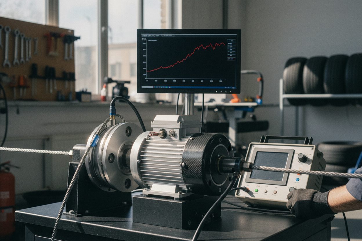
Testing and Specs
Great decisions come from good data, so learn to interpret motor specifications and verify them through testing. Core items include rated power, rated speed, continuous torque, peak torque, efficiency, voltage, current, and thermal class. A dynamometer can measure torque across RPM to map real curves, while voltage and current monitoring estimates electrical input. Comparing mechanical output to electrical input highlights losses and cooling needs. Be mindful that peak values are time-limited and depend on ambient conditions and airflow. Distinguish between marketing horsepower and usable torque at the speed you care about; the same power can appear as high torque at low RPM or low torque at high RPM. For applications like fans, prioritize speed range and efficiency; for conveyors, prioritize low-speed torque and control stability. Maintain reliability with alignment checks, bearing care, and clean ventilation paths. With clear specs, measured results, and realistic margins, your motor system delivers predictable, enduring performance.