Heat Is the Enemy: Cooling Strategies for High-Performance Motors
Heat shortens motor life and steals torque. Explore proven cooling strategies—air, liquid, and oil—to tame hotspots and sustain peak efficiency.
Why Heat Threatens Performance. In high-performance motors, heat is the inevitable tax on power density, generated by copper losses (I^2R), iron losses from hysteresis and eddy currents, and mechanical losses in bearings, seals, and windage. These losses concentrate in hotspots such as end windings, stator teeth, rotor bars or sleeves, permanent magnets, and bearings. As temperature rises, electrical resistance climbs, efficiency falls, insulation ages faster, and magnets risk demagnetization. Lubricants thin, accelerating bearing wear, while thermal expansion tightens clearances and can provoke rubbing or noise. The only cure is a low-impedance thermal path from hotspot to ambient: conduction into the frame, convection to moving air or liquid, and modest radiation at higher temperatures. Ambient conditions, enclosure design, and duty cycle compound the challenge, turning brief peaks into sustained heat soak. Understanding temperature rise, thermal gradients, and heat flux enables designers and operators to predict where failure incubates, prioritize cooling investments, and preserve torque, life, and reliability under relentless load.
Passive Paths: Materials and Geometry. Effective cooling starts with materials and geometry that move heat effortlessly. High-conductivity aluminum housings and well-fitted stator laminations shorten the conductive path, while meticulous impregnation or potting fills air gaps in windings to boost contact and damp vibration. Adding fins increases surface area for natural convection; orienting them vertically and keeping clear airflow around the frame prevents stagnant boundary layers. Between mating parts, thermal interface materials (TIMs)—ceramic-filled epoxies, graphite pads, or greases—slash contact resistance and even out hotspots at the stator–frame interface. Surface choices matter: darker, textured finishes enhance radiation, which becomes a meaningful contributor as temperatures climb. Designers can sculpt end-bell features to guide air across end windings, where many failures begin, and use ribbing or webbing to stiffen structures without choking airflow. While passive methods add no complexity or maintenance, they demand careful attention to tolerances, fastener preload, and mounting so that the thermal network remains tightly clamped over the motor's service life.
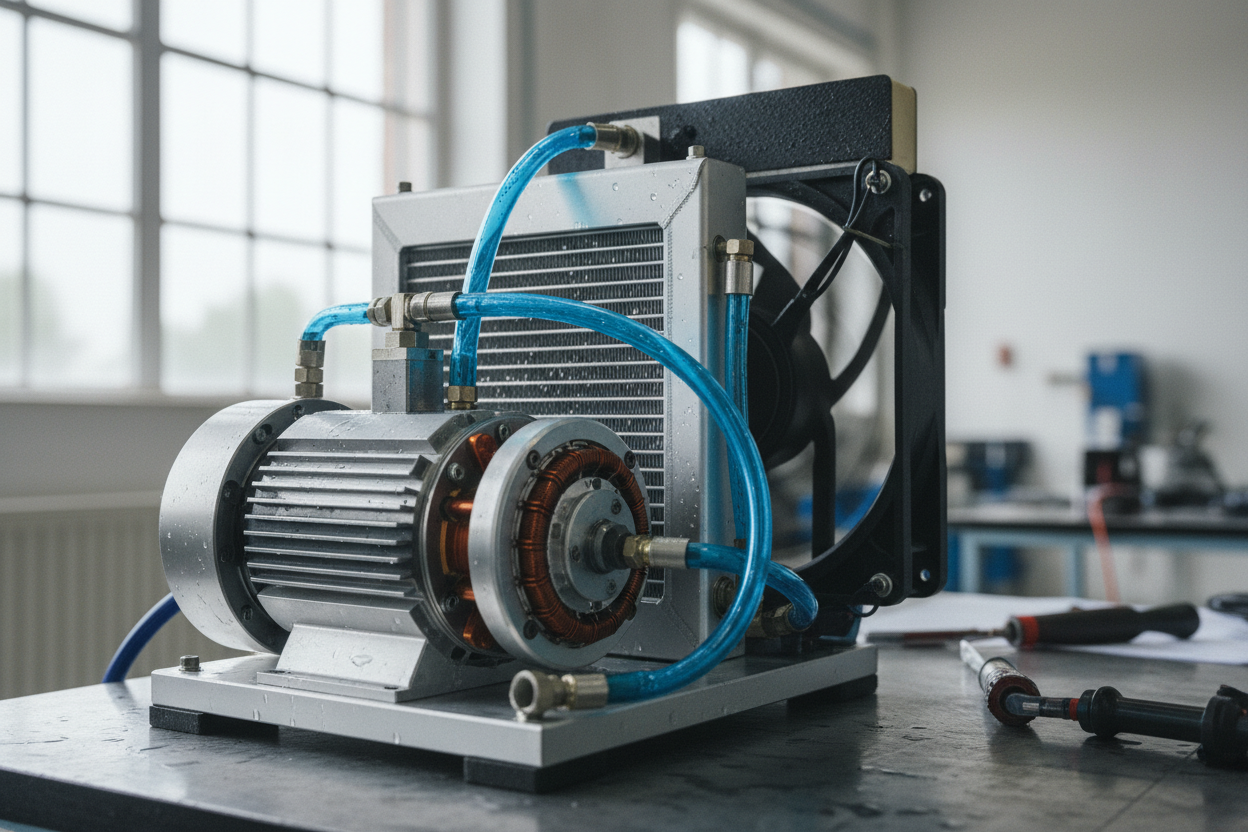
Active Cooling: Air and Liquid. When passive means are tapped out, forced convection delivers the next step in heat rejection. External fans or blowers and internal impellers can sweep air through ducts that target end windings, stator slots, and rotor surfaces, but require attention to pressure drop, filtration, and acoustic limits. Duct geometry should avoid dead zones, while shrouds and baffles focus flow where losses spike. For compact, high-load machines, liquid cooling shines: jackets, cold plates, or microchannels wrapped around the stator move heat into a circulating coolant with far higher capacity than air. Proper channel sizing promotes turbulent flow for better heat transfer, and materials must be chosen to minimize corrosion and galvanic pairs. Seals, O-rings, and connections need robust ingress protection and allowance for thermal expansion. Coolant selection—water-glycol blends or dielectric fluids—balances conductivity, reliability, and maintenance. Pump sizing, reservoir volume, and air bleed provisions complete a loop that keeps hotspot temperature in check even under aggressive duty cycles.
Smart Control and Sensing for Thermal Headroom. Cooling hardware excels when paired with controls that respect thermal limits. Embedded temperature sensors in windings, stator teeth, or bearings feed thermal models that estimate hotspot rise and trigger proactive derating before damage begins. Adjusting phase current, torque limits, or field weakening preserves performance while halting runaway temperatures. Inverters can trade PWM frequency and switching strategy to curb iron and switching losses when heat builds, while efficiency maps steer operating points toward cooler zones. Logging data enables trend analysis, spotting clogged filters, marginal fans, or rising bearing friction. Controllers should stage alarms, graceful cutbacks, and safe shutdowns rather than binary trips, protecting uptime and hardware. By coordinating motor, drive, and cooling plant as one thermal budget, teams unlock extra headroom, enabling brief overloads, faster cycles, and steadier quality without flirting with thermal runaway or premature insulation aging.
Validation, Maintenance, and System Context. The best cooling strategy begins with modeling and ends with measurement. Use FEA and CFD to map losses and airflow, then validate with thermocouples, RTDs, and infrared imaging under realistic loads, orientations, and enclosures. Pay attention to altitude, dust, and humidity, which alter convection and contaminate fins and ducts. Maintenance is nonnegotiable: clean exterior surfaces, replace filters, verify fan rotation and flow, sample or replace coolant, and watch for seal weeping. Select lubricants for expected temperatures, and maintain alignment to limit frictional heating. Cable and bus sizing reduce upstream I^2R losses that still end up as motor heat. Finally, consider the whole machine: gearbox efficiency, mounting interfaces, and nearby heat sources shape the motor's thermal environment. Reliability grows from layered defenses—robust passive paths, targeted active cooling, intelligent controls, and disciplined care—transforming heat from a lurking adversary into a managed design constraint.