Understanding Motor Efficiency and Power Factor
Learn how motor efficiency and power factor differ, why they matter for energy costs and reliability, and practical ways to measure and improve both.
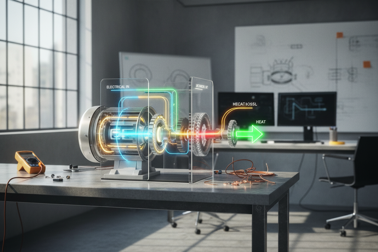
Efficiency and Power Factor Defined: Electric motors convert electrical input into mechanical output, and two numbers describe how well they do it: motor efficiency and power factor. Efficiency is the ratio of shaft power to electrical power at the terminals, capturing losses from stator copper, rotor bars, core magnetization, windage, and friction. Power factor (PF) expresses how effectively current contributes to real work, relating real power (kW) to apparent power (kVA) through the angle between voltage and current. Motors, especially induction types, draw reactive power (kvar) to establish the magnetic field, which lowers PF without necessarily changing efficiency. That means a motor can be highly efficient yet operate with poor PF at light load, or show decent PF while still wasting energy through internal losses. Understanding the power triangle (real, reactive, apparent) helps separate these concepts: efficiency answers how much input becomes torque, while PF answers how much current actually produces work. Treat them as complementary levers for optimizing motor performance.
Why They Matter in Motor Systems: High motor efficiency reduces electrical consumption, heat generation, and cooling demand, improving reliability and lowering total cost of ownership. A better power factor reduces current for the same useful output, freeing capacity in feeders, transformers, and switchgear, and trimming voltage drop and I²R losses. In plants with many motors, low PF can inflate apparent demand, constraining expansion and triggering avoidable charges or operational limits. Poor efficiency shows up as elevated temperatures, shortened insulation life, and frequent maintenance, while poor PF stresses upstream equipment even when the motor itself runs acceptably. Both metrics influence process stability: cooler windings maintain insulation integrity, and lower current improves protection selectivity and measurement accuracy. In distributed systems—fans, pumps, conveyors—right-sizing and attention to PF can defer capital upgrades by extracting more from existing infrastructure. In emergency or backup scenarios, improving PF and efficiency permits smaller generators or UPS capacity for the same mechanical workload, simplifying logistics, fuel use, and thermal management.
Measuring and Interpreting Key Metrics: To evaluate efficiency, measure electrical input (three-phase voltage, current, and real power) with a true-power analyzer, and measure mechanical output using a torque transducer and tachometer or a calibrated dynamometer. Field tests sometimes estimate output from process data (pressure, flow, speed), but direct torque-speed measurement gives higher confidence. Nameplate values and catalogs provide useful benchmarks, yet actual performance depends on load profile, supply quality, and ambient conditions. For power factor, read both displacement PF (phase shift of the fundamental) and total PF (including harmonic distortion). Nonlinear drives and heavily saturated operation introduce distortion, so relying on current and voltage phase alone can be misleading. Plot an efficiency curve versus load; most motors peak near moderate-to-high load, with declines at very light load. Similarly, PF generally rises with loading for induction machines, then stabilizes. Review the power triangle on your meter: kW indicates useful work, kvar shows magnetizing burden, and kVA sets conductor and transformer stress.
Improving Efficiency and Power Factor: Start with right-sizing: oversized motors run lightly loaded, dragging both efficiency and power factor. Where processes vary, apply variable frequency drives (VFDs) to match speed to demand, avoiding throttling losses in pumps and fans and keeping operation near optimal load. Maintain alignment, belt tension, and lubrication to cut mechanical drag, and ensure ventilation paths are clear to keep copper and iron losses in check. For PF, add capacitor banks or automatic power factor correction (APFC) near large motor groups to locally supply reactive power; consider detuned reactors or filters to avoid resonance with harmonics. Avoid overcorrection, which can drive PF leading at light load and upset protection or raise voltage. In high-duty applications, synchronous motors or synchronous condensers can deliver adjustable reactive support while providing torque. System-level tactics matter too: eliminate idle running, schedule batch operations to smooth peaks, balance phases, and specify low-resistance conductors and tight terminations to reduce I²R losses.
Design and Operational Best Practices: Select motors for the actual duty cycle—continuous, intermittent, or variable torque—and prioritize high-efficiency designs with low-loss laminations, optimized windings, and quality bearings. Match the motor to the driven load: direct-drive or properly sized gear reducers often beat over-speeding with throttling. When using VFDs, confirm cable lengths, grounding, and install dv/dt or sine filters as needed to protect insulation and reduce bearing currents. Commission with baseline tests: voltage balance, no-load current, vibration, and temperature rise. Implement predictive maintenance using trends in vibration, partial discharge (where applicable), and thermal imagery to maintain efficiency over time. Track kW, kVA, and PF in your energy management system, and set alerts for drifting metrics. Train operations to recognize signs of underloading, misalignment, and excessive starts. Document improvements with before/after demand and throughput data. Treat motor efficiency and power factor as a unified program—specification, installation, monitoring, and continuous optimization—so every kilowatt drawn translates into reliable, productive torque.